LIMIT® can be operated using a node locked or network license. In case of the nodelocked license LIMIT® support needs the MAC address of the hardware to generate the license file. In case of the network license, LIMIT® uses its on server software, which is installed on a windows machine within the network. Again the MAC address of the server is needed. Since LIMIT® consist of different modules, also the licensing is modular. For more details see: https://www.limit-fatigue.com/licensing/
During the LIMIT® installation all interfaces available in the package are tested. Only interfaces that pass the check are listed in the JobManager. When a new ANSYS version is installed, the interface check does not run automatically and LIMIT® CAE does not recognize the change. The user has two possibilities to update LIMIT-CAE:
1. Manual update or
2. Reinstalling LIMIT.
Option 1.) is much faster and can be performed in the following steps:
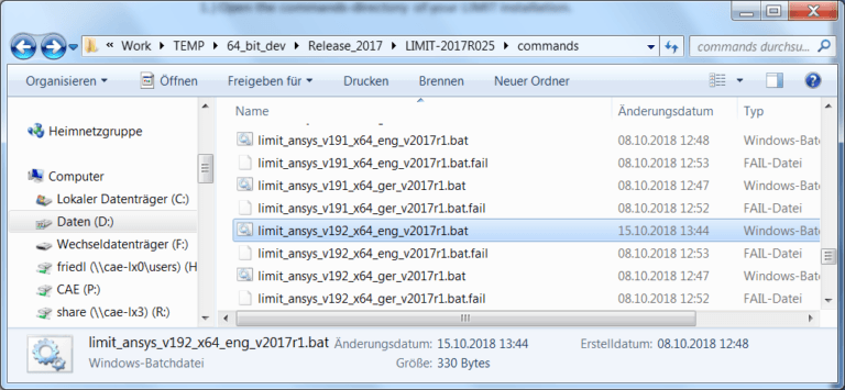
a) Open the commands-directory of your LIMIT® installation and double-click the batchfile for the specific Ansys version needed (here e.g. V192).
b) See if the standard prompt of the LIMIT® solver appears!
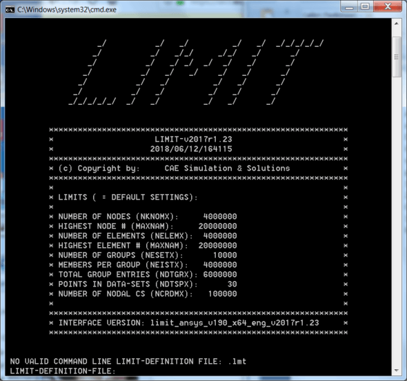
c) If the prompt looks like above, the solver finds all necessary libraries and can be used. In order to make the preference visible in LIMIT-CAE the file named [preference].fail (here e.g. limit_ansys_v192_x64_eng_v2017r1.bat.fail) must be deleted.
d) Now the preference should appear in the JobManager!
LIMIT® uses an internal threshold value for calculated margins of safety of 5.0. The threshold for calculated degrees of utilization is inverse proportional with a value of 0.2. Degrees of utilization are only stored if they are above 0.2.
The threshold value can be changed in the JobManager using the parameter “MAX. Safety Value”. The reciprocal value will define the threshold for the degree of utilization. If the assessment should resolve degrees of utilization down to 0.05 (=5%), then a maximum safety value of 20 is needed. These settings have to be defined before running the job.
The LIMIT® solver operates with the stresses on the top and bottom side of shells. Any kind of offset is taken into account automatically. In LIMIT-CAE the shell offset is not used. Shells always appear as mid surface model. This is only a displaying issue. The results are correct.
This issue has been reported and one reason might be, that there is no Microsoft Visual C++ installed on the computer. If the problem remains, please contact LIMIT® support.
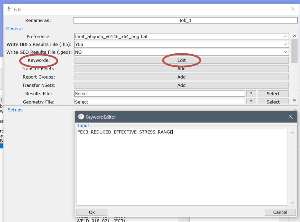
Keywords can either be added directly to the .lmt-file by editing it with a text editor or through the JobManager from within LIMIT-CAE. Click on the “Edit” button next to “Keywords” in the “Edit Job” window and add keywords into the “KeywordEditor” window.
LIMIT’s documentation is installed in ***LIMIT-directory***\doku\. For example D:\LIMIT\LIMIT-2019R011\doku\.
The files can be accessed directily or through the LIMIT-GUI by clicking on Help-> Help Index
- Open the ResultManager
- Click “Additional…”,
- Click “Select elements by result range”
- Enter the desired range, click OK and Close. The selection buffer is now filled with elements with the given result range.
- Then right-click “Replace” in the viewport to show only the selected elements.
Currently this option is not available. The report is generated for all setups of a job.
LIMIT® plugins are python scripts that can be used to extend LIMIT’s functionality. The scripts can be found in LIMIT-CAE under Plugins.
The corresponding .py-files are located in ***LIMIT-directory***\Plugins\. For example D:\LIMIT\LIMIT-2019R011\Plugins\.
It is possible to compare multiple results with multiple LIMIT-Viewer windows.
- Open two or more results in separate LIMIT-Viewer windows.
- Click Options-> Run Viewmanipulation Thread in one LIMIT-Viewer window and then select a different window which should act as master.
- Manipulation of the master view is coupled with the other LIMIT-Viewer window.
- The view of multiple LIMIT-Viewer windows can be coupled with the master view by clicking Run Viewmanipulation Thread in each window and then selecting the master view.
- To stop the Viewmanipulation Thread either go to Options-> Stop Viewmanipulation Thread or hit the “M”-key on your keyboard.
The red line indicates the unwelded side of the continuous sheet. It is only displayed when the entered FAT-classes or notch cases for point 5 match those of the unwelded side, e.g., 140, 140, 100 (EC3) or A+, A+, G+ (DVS1612).
The values which activate the red line depend on the used code and are listed in the file “SurfaceMarker.dat” found in ***LIMIT-directory***\setup_library\***Code**\. For example D:\LIMIT\LIMIT-2019R011\setup_library\EC3. The “SurfaceMarker.dat” files can be edited by the user.
In LIMIT-Viewer the results MAX.D.O.UTILIZATION or MAX.D.O.UTILIZATION_(EL) can be selected to view the resulting degree of utilization (D.O.U.). The difference is only in the coloring of the analyzed elements.
Setting the legend in LIMIT-Viewer to MAX.D.O.UTILIZATION colors the elements with a color gradient, based on the values of D.O.U. contributed by each node connected to the element.
Setting the legend in LIMIT-Viewer to MAX.D.O.UTILIZATION_(EL) colors the element with one fill color, based on the max. value of D.O.U. contributed by all nodes connected to the element.
Go to Plugins-> ToggleLinearSolidRepresentation.py to speed up the LIMIT-GUI.
In classical nominal stress concepts, the notch case with regard to the longitudinal weld direction changes at the end of the weld, because the strong geometrical notch is influential at this location.
Therefore, a second longitudinal notch case can be given when working with local nominal stress consepts. For example, entering ‘‘100(56),71,80“ in your weld definition will assign a FAT Class of 100 to the weld setup in the longitudinal weld direction. The value inside the brackets, 56, will only be assigned to the elements at the weld end.
The easiest way is using software tools like TeamViewer, AnyDesk or VNC. (VNC Server needs to be installed on the machine to be able to access it with a VNC client)
Using Windows Remote Desktop the following considerations apply:
As LIMIT® requires at least OpenGL Version 3.0 for full graphics support there may sometimes be problems starting LIMIT® with Windows Remote Desktop.
The OpenGL Version used of Windows Remote Desktop is per default 1.1. It is therefore needed to activate full hardware acceleration (which always includes higher openGL versions) to start LIMIT® via remote Desktop. The default settings of current Windows10 releases usually do this properly. However, in some cases it might be necessary to activate the special GPO “Use the hardware default graphics adapter for all Remote Desktop Services sessions”. It is available in Windows 10 or Windows Server 2012 R2 and can be found at: Local Computer Policy\Computer Configuration\Administrative Templates\Windows Components\Remote Desktop Services\Remote Desktop Session Host\Remote Session Environment; enable “Use the hardware default graphics adapter for all Remote Desktop Services sessions” and restart the machine.
Our team has tested and confirmed numerous AMD graphics cards and NVIDIA Quadro graphics cards as working with this Group Policy setting.
In case of NVIDIA GeForce graphics cards, we observed that hardware acceleration was not activated even with the GPO set as described above. This was due to a graphics card driver issue resolved in late 2020. It is therefore always recommended to update the graphics drivers in case of problems.
In all cases LIMIT® can be used via Remote Desktop if LIMIT® is started locally before using the remote connection.
As default the searching algorithms in LIMIT-CAE will define the set with the lower number of elements as the first element set, which is indicated with “_01” at the end of the weld set name.
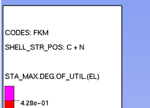
In LIMIT-Viewer the information SHELL_STR_POS and SOLID_STR_POS, respectively, are displayed in the legend. LIMIT® displays this information to indicate which stresses where used:
- SHELL_STR_POS: C -> Element center stresses
- SHELL_STR_POS: N -> Element nodal stresses
- SHELL_STR_POS: C + N -> Element center and nodal stresses
LIMIT® uses stress values at nodes. The default Abaqus output exports the stresses at the integration points. To request the correct output use the following lines in your .inp-file:
*OUTPUT, FIELD
*ELEMENT OUTPUT, POSITION=NODES
S
Depending on your preprocessor, make sure that the .inp-file is generated without “Parts” and “Assemblies”
- When autocreating sensors, make sure that the selected elements don’t belong to a feature edge of the corresponding solid.
- Autocreation of senors works best on sets containing parts of constant thickness. Sets can be manually created within LIMIT® to exclude thickness changes, e.g. ribs on casted parts.
- Autocreation of sensors within LIMIT-CAE works best with solid models in which the different components are meshed with incompatible meshes, meaning that the different components don’t share nodes.
Such a FE model would not run properly, hence we recommend to create two FE models when encountering problems with autocreation of sensors:
- FE model 1: original FE model, components share nodes.
- FE model 2: modified FE model, components are detached from each other. Use the appropriate detach function in your FE preprocessor, no remeshing required.
The FE analysis should be carried out with FE model 1. For the autocreation of sensors import FE model 2 into LIMIT-CAE. The results of FE model 1 are linked in the LoadManager and the JobManager.
Sensors are not linked to any FE nodes or elements, so there is no need to worry about node and element numbers.
- Select the setup in the SetupManager
- Click the RMB and select “Split”
- Now click into the viewport and press the “Esc”-key on the keyboard to clear the selection buffer
- Select the elements that should be moved to a new setup by selecting them directly with the LMB or by dragging a selection window around them using the LMB.
- Click on Ok.
The easiest way is to import a corner weld setup from the library.
The values “A-Top”, “A-Bot”, “D-Top” and “D-Bot” define the basic weld geometry, depending on which shell surface the weld should be placed. They can be given as a function of the shell thickness “t”. Click Help->Show Weld Definition in the LIMIT-GUI to see an image on how these values are defined. It is important to note that the “D” values are measured from the middle of the sheet.
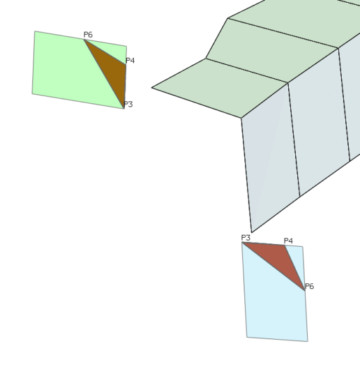
A corner weld is defined with a default “A” value of “t*0.7” and a “D” value of “-t*0.5”. The weld symbol is placed on both sheets.
The resulting red triangle is only a simplified view and does not represent a realistic view of the defined weld. It’s shape is distorted as point P6 is always placed on the outer side of the shell. It is important to note, that point P3 is placed right in the corner.
The values “A-Top”, “A-Bot”, “D-Top” and “D-Bot” define the basic weld geometry, depending on which shell surface the weld should be placed. They can be given as a function of the shell thickness “t”. Click Help->Show Weld Definition in the LIMIT-GUI to see an image on how these values are defined. It is important to note that the “D” values are measured from the middle of the sheet.
A HV-weld is defined with an “A” value of “t” and a “D” value of “-t*0.5”. This results in a full penetration weld. Adding a fillet weld is done by simply increasing the “A” value, e.g. by setting it to “t+4”. This adds a fillet weld with size a4 to the HV-weld.
A HY-weld is defined with an “A” value smaller than “t”, e.g. “t*0.8”. In addition, a “D” value of “-t*0.3” needs to be given to set the root point at the correct position. Adding a fillet weld is done by simply increasing the “A” value, e.g. by setting it to “t*0.8+4”. This adds a fillet weld with size a4 to the HY-weld.
The resulting red triangle is only a simplified view and does not represent a realistic view of the defined weld. You can save the setup to your setup-library by clicking the export button in the EditSetup window.

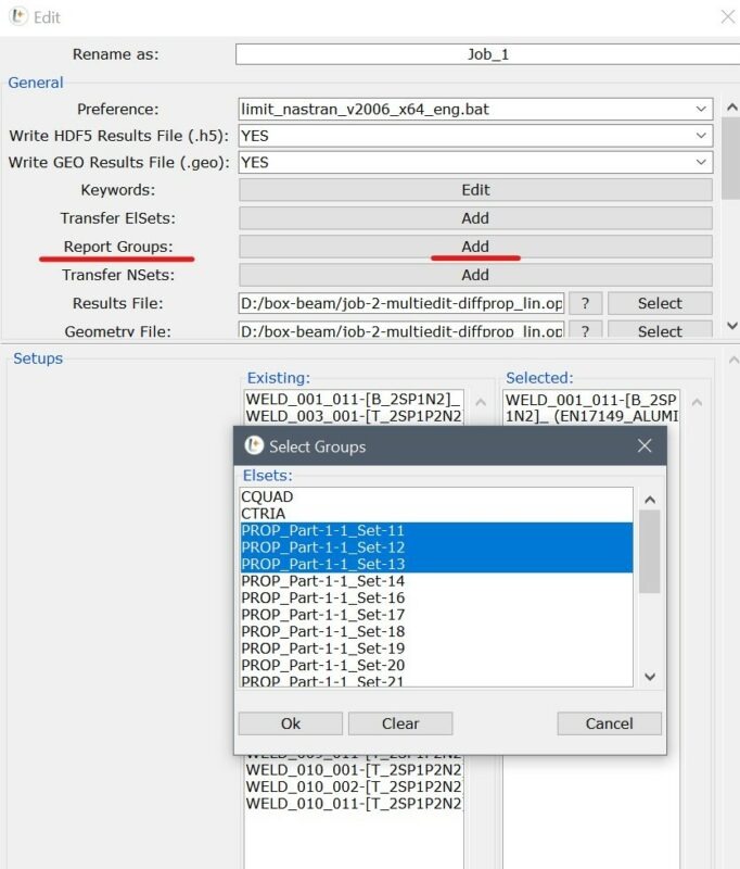
ElSets for which a detailed result should be generated can be specified in the “Edit Job” window in the JobManager. Choose the desired ElSets under “Report Groups”. The results are written in the JobName_detailed_results_user_elements.txt file.
In case that there have been some additions to your FE model, e.g., some stiffeners have been added, new welds need to be defined in LIMIT-CAE:
- Re-import the FE model (File -> Import), replace the existing FE Data, keep the existing LIMIT® Model Data, skip the weld regeneration.
- Isolate the new parts/sheets.
- Select elements of the new parts/sheets -> RMB->Selection -> e.g. By Same Property.
- RMB->ReplaceElmWithNodes.
- Select all displayed elements by a window.
- RMB->Mark conn. Nodes.
- RMB ->Mark conn. Elements to add all elements attached to these nodes.
- RMB->Show. This shows all elements which are connected to your new parts/sheets.
- Sets -> Generate Weld Sets by Property (Use a different prefix to better find the new weld sets in the SetupManager).
- Open SetupManager -> Auto.
- Mark all new sets.
- Auto-Create.
- Configure the new sets, delete duplicates.
- Check the status of your old setups in the SetupManager in case elements have been removed from existing setups. This may happen if a remesh affects elements which have been already defined in a setup.
You can get your personal quote for a license here!
