When importing a shell model into LIMIT-CAE also the shell property information is read and stored. The simplest and most robust way to detect welds is by searching for nodes attached to shells with different properties. Obviously it is important to organize the Finite Element model in the preprocessing phase in such a way, that this feature can be used efficiently. For example, all ribs with the same shell thickness and same weld quality should use the same property definition, rather than defining an individual property ID for each rib. A low number of properties will also result into a lower number of different weld definitions.
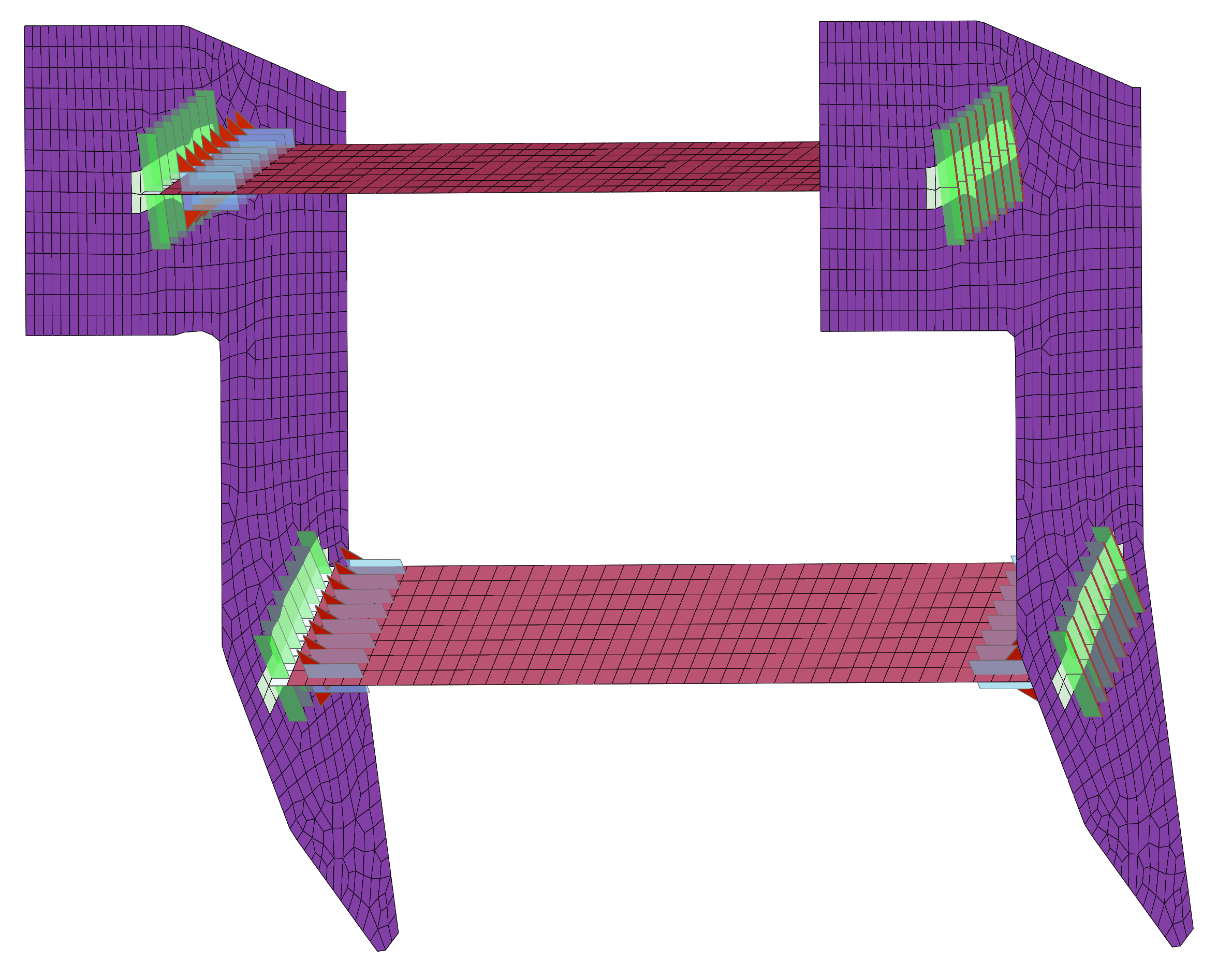
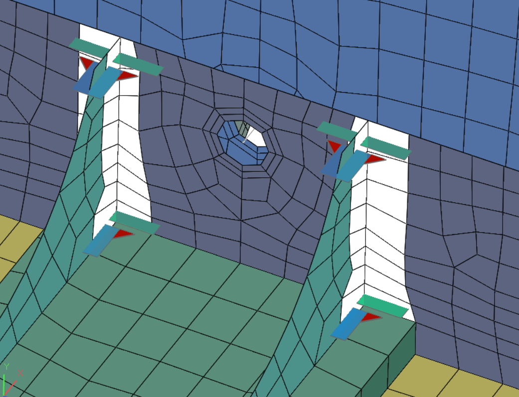
In LIMIT® a weld definition is called Setup and can include one or more spatially separated welds. In this way symmetry or repeating weld details can be used in order to reduce the number of weld definitions. In LIMIT® the weld in the model is marked via weld sets, consisting of the row of nodes on the weld plus the individual rows of shell elements attached to these nodes grouped by their properties.
The figure below indicates a double-sided weld at a T-Joint. LIMIT® visualizes the location of the weld as well as the thickness of the sheets AND the weld thickness along the complete welding path.